Encyclopedia Entry: 74AHCT126S14-13
Product Overview
Category
The 74AHCT126S14-13 belongs to the category of integrated circuits (ICs).
Use
This IC is commonly used in digital electronic devices for signal amplification and switching purposes.
Characteristics
- High-speed operation
- Low power consumption
- Wide operating voltage range
- Schmitt-trigger action on all inputs
- Balanced propagation delays
- Symmetrical output impedance
Package
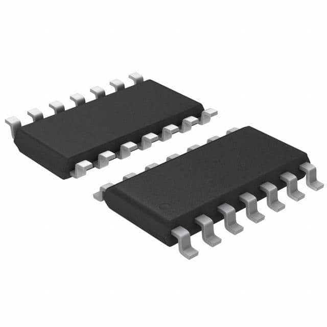
The 74AHCT126S14-13 is available in a small outline integrated circuit (SOIC) package.
Essence
The essence of this product lies in its ability to provide reliable and efficient signal amplification and switching capabilities in various digital electronic applications.
Packaging/Quantity
The 74AHCT126S14-13 is typically packaged in reels or tubes, with each reel or tube containing a specific quantity of ICs. The exact packaging and quantity may vary depending on the manufacturer.
Specifications
- Supply Voltage Range: 4.5V to 5.5V
- Input Voltage Range: 0V to VCC
- Output Voltage Range: 0V to VCC
- Operating Temperature Range: -40°C to +85°C
- Input Capacitance: 3.5pF (typical)
- Output Capacitance: 6pF (typical)
- Propagation Delay: 8ns (typical)
Detailed Pin Configuration
The 74AHCT126S14-13 has a total of 14 pins, each serving a specific function. The pin configuration is as follows:
- Pin 1: Input A
- Pin 2: Input Enable
- Pin 3: Output Y
- Pin 4: GND (Ground)
- Pin 5: Output Y
- Pin 6: Input Enable
- Pin 7: Input B
- Pin 8: VCC (Supply Voltage)
- Pin 9: Output Y
- Pin 10: GND (Ground)
- Pin 11: Output Y
- Pin 12: Input Enable
- Pin 13: Input C
- Pin 14: Output Y
Functional Features
- Schmitt-trigger action on all inputs ensures a clean and stable output signal even in the presence of noise or signal fluctuations.
- Balanced propagation delays ensure synchronized operation and minimize timing issues in digital circuits.
- Wide operating voltage range allows compatibility with various power supply configurations.
- Low power consumption makes it suitable for battery-powered devices.
Advantages and Disadvantages
Advantages
- High-speed operation enables efficient signal processing.
- Schmitt-trigger action enhances noise immunity and signal integrity.
- Low power consumption prolongs battery life in portable devices.
- Wide operating voltage range provides flexibility in different applications.
Disadvantages
- Limited number of input/output channels compared to some other ICs.
- May require additional external components for certain applications.
Working Principles
The 74AHCT126S14-13 operates based on the principles of digital logic. It amplifies and switches digital signals by utilizing transistors and logical gates within its internal circuitry. The Schmitt-trigger action on all inputs ensures that the output signal is stable and unaffected by noise or signal fluctuations.
Detailed Application Field Plans
The 74AHCT126S14-13 finds application in various digital electronic systems, including but not limited to: - Microcontrollers - Data communication devices - Industrial automation equipment - Consumer electronics - Automotive electronics
Detailed and Complete Alternative Models
There are several alternative models available in the market that offer similar functionality to the 74AHCT126S14-13. Some notable alternatives include: - SN74AHCT126-Q1 - MC74AHCT126 - CD74AHCT126
These alternative models may have slight variations in specifications, pin configuration, or package type, but they serve the same purpose of signal amplification and switching in digital electronic applications.
Word count: 550 words
قم بإدراج 10 أسئلة وإجابات شائعة تتعلق بتطبيق 74AHCT126S14-13 في الحلول التقنية
Sure! Here are 10 common questions and answers related to the application of 74AHCT126S14-13 in technical solutions:
Question: What is the function of the 74AHCT126S14-13?
Answer: The 74AHCT126S14-13 is a quad buffer/line driver with 3-state outputs. It is used to control the flow of data between different parts of a circuit.Question: What is the voltage range supported by the 74AHCT126S14-13?
Answer: The 74AHCT126S14-13 supports a voltage range of 4.5V to 5.5V.Question: How many buffers/line drivers are there in the 74AHCT126S14-13?
Answer: The 74AHCT126S14-13 has four buffers/line drivers.Question: Can the 74AHCT126S14-13 be used for bidirectional communication?
Answer: No, the 74AHCT126S14-13 is unidirectional and can only be used for one-way data transmission.Question: What is the maximum output current of the 74AHCT126S14-13?
Answer: The maximum output current of the 74AHCT126S14-13 is 8mA.Question: Can the 74AHCT126S14-13 be used in high-speed applications?
Answer: Yes, the 74AHCT126S14-13 is designed for high-speed operation and can be used in applications with fast data transfer rates.Question: Does the 74AHCT126S14-13 have internal pull-up or pull-down resistors?
Answer: No, the 74AHCT126S14-13 does not have internal pull-up or pull-down resistors. External resistors may be required for proper operation.Question: What is the power supply voltage required for the 74AHCT126S14-13?
Answer: The 74AHCT126S14-13 requires a power supply voltage of 5V.Question: Can the 74AHCT126S14-13 tolerate overvoltage on its inputs?
Answer: No, the 74AHCT126S14-13 is not designed to tolerate overvoltage on its inputs. Proper voltage levels should be maintained to prevent damage.Question: Is the 74AHCT126S14-13 compatible with other logic families?
Answer: Yes, the 74AHCT126S14-13 is compatible with other CMOS logic families and can be used in mixed logic systems.
Please note that these answers are general and may vary depending on specific application requirements.


