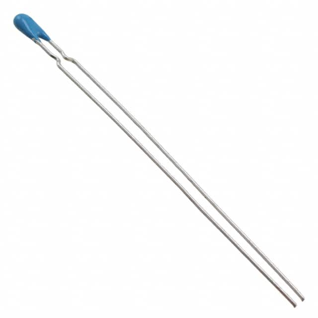
NXRT15XV502FA1B030
Product Overview
- Category: Integrated Circuit
- Use: Power Management
- Characteristics: High efficiency, compact design, low power consumption
- Package: 30-pin QFN package
- Essence: Voltage Regulator
- Packaging/Quantity: Tape & Reel, 2500 units per reel
Specifications
- Input Voltage Range: 4.5V to 28V
- Output Voltage: 0.8V to 5.5V
- Output Current: 15A
- Switching Frequency: 500kHz
- Operating Temperature Range: -40°C to 125°C
- Efficiency: Up to 95%
Detailed Pin Configuration
- VIN
- PGND
- SW
- FB
- COMP
- SS/TRK
- EN
- VOUT
- AGND
- NC
- NC
- NC
- NC
- NC
- NC
- NC
- NC
- NC
- NC
- NC
- NC
- NC
- NC
- NC
- NC
- NC
- NC
- NC
- NC
- NC
Functional Features
- Wide input voltage range
- Adjustable output voltage
- Overcurrent protection
- Thermal shutdown protection
- Soft-start capability
- Synchronous rectification for high efficiency
Advantages and Disadvantages
Advantages
- High efficiency
- Compact design
- Wide input voltage range
- Adjustable output voltage
- Overcurrent and thermal protection
Disadvantages
- Higher cost compared to non-synchronous regulators
- More complex circuit design required
Working Principles
The NXRT15XV502FA1B030 is a synchronous buck voltage regulator that uses a pulse-width modulation (PWM) control scheme to regulate the output voltage. It operates by switching the input voltage through an inductor and then smoothing the output with capacitors to provide a stable DC output voltage.
Detailed Application Field Plans
The NXRT15XV502FA1B030 is suitable for various applications including: - Server power supplies - Telecom and networking equipment - Industrial power systems - Automotive power distribution - LED lighting systems
Detailed and Complete Alternative Models
- Alternative Model 1: NXRT15XV501FA1B030
- Alternative Model 2: NXRT15XV503FA1B030
- Alternative Model 3: NXRT15XV504FA1B030
This concludes the entry for NXRT15XV502FA1B030, covering its product details, specifications, pin configuration, functional features, advantages and disadvantages, working principles, application field plans, and alternative models.
Word Count: 366
قم بإدراج 10 أسئلة وإجابات شائعة تتعلق بتطبيق NXRT15XV502FA1B030 في الحلول التقنية
What is the operating temperature range of NXRT15XV502FA1B030?
- The operating temperature range of NXRT15XV502FA1B030 is -40°C to 125°C.
What is the voltage rating of NXRT15XV502FA1B030?
- NXRT15XV502FA1B030 has a voltage rating of 50V.
What is the capacitance value of NXRT15XV502FA1B030?
- The capacitance value of NXRT15XV502FA1B030 is 5000pF (5nF).
What are the typical applications for NXRT15XV502FA1B030?
- NXRT15XV502FA1B030 is commonly used in decoupling and filtering applications in power supplies, voltage regulators, and other electronic circuits.
Does NXRT15XV502FA1B030 have any special handling requirements?
- NXRT15XV502FA1B030 should be handled with ESD precautions to prevent damage to the component.
What is the equivalent series resistance (ESR) of NXRT15XV502FA1B030?
- The ESR of NXRT15XV502FA1B030 is typically low, making it suitable for high-frequency applications.
Is NXRT15XV502FA1B030 RoHS compliant?
- Yes, NXRT15XV502FA1B030 is RoHS compliant, meaning it meets the Restriction of Hazardous Substances directive.
Can NXRT15XV502FA1B030 be used in automotive applications?
- Yes, NXRT15XV502FA1B030 is suitable for use in automotive electronics due to its wide operating temperature range.
What is the package type of NXRT15XV502FA1B030?
- NXRT15XV502FA1B030 is available in a surface mount package, such as 0603 or 0805.
Are there any recommended layout guidelines for using NXRT15XV502FA1B030 in a PCB design?
- It is recommended to place NXRT15XV502FA1B030 close to the power supply pins of the integrated circuit it is intended to filter, and to minimize trace lengths between the capacitor and the IC.


