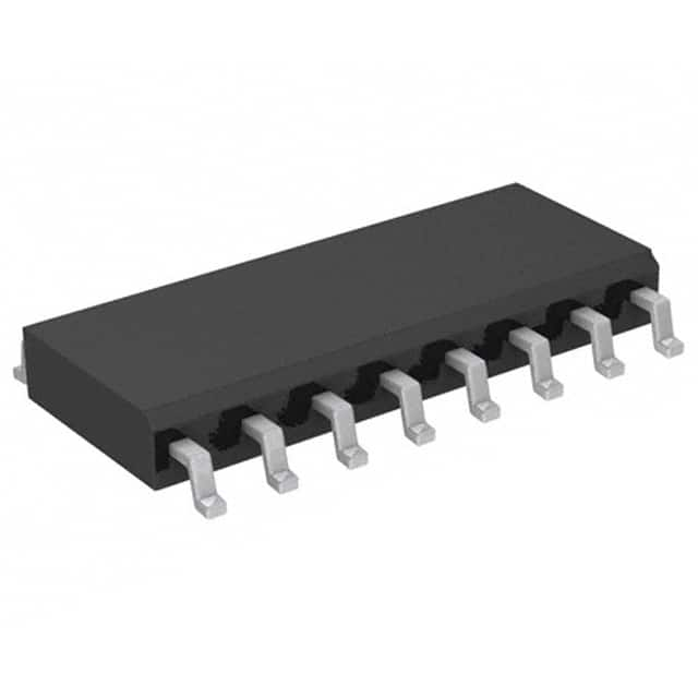
HCF4021BM1
Product Overview
- Category: Integrated Circuit (IC)
- Use: Shift Register
- Characteristics: Serial to Parallel Data Conversion, 8-Bit Storage, CMOS Technology
- Package: SO-16 (Small Outline 16-pin package)
- Essence: Efficient data storage and retrieval
- Packaging/Quantity: Available in reels of 2500 units
Specifications
- Supply Voltage: 3V to 18V
- Operating Temperature Range: -55°C to +125°C
- Input Voltage: 0V to VDD
- Output Voltage: 0V to VDD
- Maximum Clock Frequency: 5MHz
- Latch-Up Immunity: 500mA
- Static Input Current: ±1µA
- Static Output Current: ±10mA
Detailed Pin Configuration
The HCF4021BM1 IC has a total of 16 pins. The pin configuration is as follows:
- Clock (CLK)
- Serial Data Input (SER)
- Enable (EN)
- Parallel Data Output 0 (Q0)
- Parallel Data Output 1 (Q1)
- Parallel Data Output 2 (Q2)
- Parallel Data Output 3 (Q3)
- Parallel Data Output 4 (Q4)
- Parallel Data Output 5 (Q5)
- Parallel Data Output 6 (Q6)
- Parallel Data Output 7 (Q7)
- Ground (GND)
- Parallel Load (PL)
- Serial Data Output (Q7S)
- Supply Voltage (VDD)
- Not Connected (NC)
Functional Features
- Serial-to-Parallel Data Conversion: Allows conversion of serial input data into parallel output data.
- 8-Bit Storage: Can store up to 8 bits of data.
- CMOS Technology: Utilizes Complementary Metal-Oxide-Semiconductor technology for low power consumption and high noise immunity.
Advantages and Disadvantages
Advantages: - Efficient data storage and retrieval - Low power consumption - High noise immunity - Compact package size
Disadvantages: - Limited maximum clock frequency (5MHz) - Requires external clock signal for operation
Working Principles
The HCF4021BM1 is a shift register IC that performs serial-to-parallel data conversion. It operates by shifting the input data bit-by-bit into its internal storage registers. The clock signal controls the shifting process, while the enable signal enables or disables the output stage. The parallel load input allows direct loading of data into the storage registers. The stored data can be accessed in parallel through the output pins.
Detailed Application Field Plans
The HCF4021BM1 IC finds applications in various fields, including:
- Industrial Automation: Used for data acquisition and control systems.
- Communication Systems: Enables efficient data transmission and reception.
- Consumer Electronics: Integrated into devices requiring data storage and retrieval.
- Automotive Electronics: Used in automotive control units for data processing.
Detailed and Complete Alternative Models
- CD4021B: Similar shift register IC with comparable specifications.
- SN74HC165: Alternative IC offering similar functionality but with different pin configuration.
- HEF4021BP: Equivalent IC from a different manufacturer.
These alternative models can be considered based on specific requirements and availability.
Word count: 335 words
قم بإدراج 10 أسئلة وإجابات شائعة تتعلق بتطبيق HCF4021BM1 في الحلول التقنية
Sure! Here are 10 common questions and answers related to the application of HCF4021BM1 in technical solutions:
Q1: What is HCF4021BM1? A1: HCF4021BM1 is a CMOS 8-stage static shift register commonly used in digital applications.
Q2: What is the purpose of using HCF4021BM1 in technical solutions? A2: HCF4021BM1 is used to expand the number of input or output pins in microcontrollers or other digital devices.
Q3: How many input/output pins does HCF4021BM1 have? A3: HCF4021BM1 has 8 input/output pins.
Q4: Can HCF4021BM1 be cascaded to increase the number of input/output pins? A4: Yes, multiple HCF4021BM1 chips can be cascaded together to increase the number of input/output pins.
Q5: What is the maximum clock frequency supported by HCF4021BM1? A5: The maximum clock frequency supported by HCF4021BM1 is typically around 5 MHz.
Q6: Is HCF4021BM1 compatible with both 3.3V and 5V logic levels? A6: Yes, HCF4021BM1 is compatible with both 3.3V and 5V logic levels.
Q7: Can HCF4021BM1 be used for both input and output operations? A7: Yes, HCF4021BM1 can be used for both input and output operations depending on the configuration.
Q8: Does HCF4021BM1 require external pull-up or pull-down resistors? A8: Yes, HCF4021BM1 requires external pull-up or pull-down resistors for proper operation.
Q9: What is the power supply voltage range for HCF4021BM1? A9: The power supply voltage range for HCF4021BM1 is typically between 3V and 18V.
Q10: Can HCF4021BM1 be used in both digital and analog applications? A10: No, HCF4021BM1 is primarily designed for digital applications and may not be suitable for analog applications.
Please note that these answers are general and may vary depending on specific datasheet specifications and application requirements.


