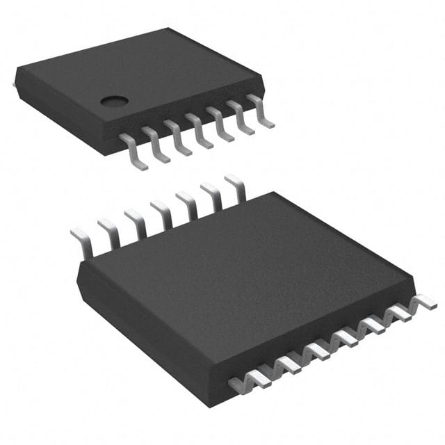
CD4025BPWR
Product Overview
- Category: Integrated Circuit (IC)
- Use: Digital Logic
- Characteristics: Quad 3-Input NOR Gate
- Package: TSSOP-14
- Essence: High-performance CMOS technology
- Packaging/Quantity: Tape and Reel, 2500 pieces per reel
Specifications
- Supply Voltage Range: 3V to 18V
- Input Voltage Range: 0V to VDD
- Output Voltage Range: 0V to VDD
- Operating Temperature Range: -55°C to +125°C
- Propagation Delay Time: 25ns (typical)
Detailed Pin Configuration
The CD4025BPWR has a total of 14 pins. The pin configuration is as follows:
- Pin 1: Input A
- Pin 2: Input B
- Pin 3: Input C
- Pin 4: Output Y1
- Pin 5: Output Y2
- Pin 6: Output Y3
- Pin 7: GND (Ground)
- Pin 8: Output Y4
- Pin 9: VDD (Supply Voltage)
- Pin 10: Input D
- Pin 11: Input E
- Pin 12: Input F
- Pin 13: Output Y5
- Pin 14: Output Y6
Functional Features
- Quad 3-input NOR gate with buffered outputs
- High noise immunity
- Wide supply voltage range
- Low power consumption
- High-speed operation
Advantages and Disadvantages
Advantages: - Versatile logic gate suitable for various digital applications - High-performance CMOS technology ensures reliable operation - Buffered outputs provide improved signal integrity
Disadvantages: - Limited number of inputs (3 inputs per gate) - Propagation delay may affect timing-sensitive applications
Working Principles
The CD4025BPWR is a quad 3-input NOR gate that performs logical NOR operations on its input signals. It utilizes CMOS technology, which allows for low power consumption and high noise immunity. The buffered outputs ensure that the gate's output signals are not affected by external factors.
Detailed Application Field Plans
The CD4025BPWR can be used in various digital logic applications, including but not limited to: - Arithmetic circuits - Data processing systems - Control systems - Communication systems - Memory circuits
Detailed and Complete Alternative Models
Some alternative models to the CD4025BPWR include: - CD4001B: Quad 2-input NOR gate - CD4078B: 8-input NOR/OR gate - CD4011B: Quad 2-input NAND gate - CD4081B: Quad 2-input AND gate
These alternative models offer similar functionality and can be used as substitutes depending on specific requirements.
Word count: 248 words
قم بإدراج 10 أسئلة وإجابات شائعة تتعلق بتطبيق CD4025BPWR في الحلول التقنية
Sure! Here are 10 common questions and answers related to the application of CD4025BPWR in technical solutions:
Q: What is CD4025BPWR? A: CD4025BPWR is a CMOS Triple 3-Input NOR gate IC, commonly used in digital logic circuits.
Q: What is the operating voltage range for CD4025BPWR? A: The operating voltage range for CD4025BPWR is typically between 3V and 18V.
Q: Can CD4025BPWR be used in both analog and digital circuits? A: No, CD4025BPWR is specifically designed for digital logic applications and is not suitable for analog circuits.
Q: How many inputs does CD4025BPWR have? A: CD4025BPWR has three inputs, labeled A, B, and C.
Q: What is the output configuration of CD4025BPWR? A: CD4025BPWR has three outputs, each corresponding to one of the input combinations.
Q: What is the maximum frequency at which CD4025BPWR can operate? A: CD4025BPWR can typically operate at frequencies up to 10 MHz.
Q: Can CD4025BPWR be used as a level shifter? A: Yes, CD4025BPWR can be used as a level shifter to convert signals from one voltage level to another.
Q: Is CD4025BPWR tolerant to static discharge? A: CD4025BPWR has built-in ESD protection, making it relatively tolerant to static discharge.
Q: Can CD4025BPWR drive high capacitive loads? A: CD4025BPWR has limited output current capabilities, so it may not be suitable for driving high capacitive loads directly.
Q: Are there any specific precautions to consider when using CD4025BPWR? A: It is important to ensure that the power supply voltage does not exceed the specified range and to avoid exceeding the maximum input voltage levels to prevent damage to the IC. Additionally, proper decoupling capacitors should be used near the power supply pins.


