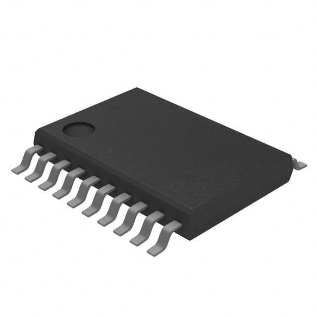
SN74AC574PWRG4
Product Overview
- Category: Integrated Circuit
- Use: Flip-Flop
- Characteristics: High-speed, low-power, octal D-type flip-flop
- Package: TSSOP (Thin Shrink Small Outline Package)
- Essence: Digital Logic IC
- Packaging/Quantity: Tape and Reel, 2500 pieces per reel
Specifications
The SN74AC574PWRG4 is a high-speed, low-power octal D-type flip-flop integrated circuit. It operates on a supply voltage range of 2V to 6V and has a typical propagation delay of 5.8 ns. The flip-flop features eight independent D-type positive-edge-triggered flip-flops with 3-state outputs. It is designed for use in various digital logic applications that require reliable and efficient storage of data.
Detailed Pin Configuration
The SN74AC574PWRG4 has a total of 20 pins, which are arranged as follows:
- GND - Ground
- D0 - Data Input 0
- D1 - Data Input 1
- D2 - Data Input 2
- D3 - Data Input 3
- D4 - Data Input 4
- D5 - Data Input 5
- D6 - Data Input 6
- D7 - Data Input 7
- OE - Output Enable
- CP - Clock Pulse Input
- Q0 - Output 0
- Q1 - Output 1
- Q2 - Output 2
- Q3 - Output 3
- Q4 - Output 4
- Q5 - Output 5
- Q6 - Output 6
- Q7 - Output 7
- VCC - Supply Voltage
Functional Features
The SN74AC574PWRG4 offers the following functional features:
- High-speed operation: The flip-flop is designed to operate at high clock frequencies, making it suitable for time-critical applications.
- Low-power consumption: It has low power dissipation, making it energy-efficient and suitable for battery-powered devices.
- 3-state outputs: The flip-flop provides 3-state outputs, allowing multiple devices to share a common bus without interference.
- Positive-edge-triggered: The flip-flop triggers on the rising edge of the clock pulse, ensuring accurate data storage.
Advantages and Disadvantages
Advantages: - High-speed operation enables efficient data processing. - Low-power consumption prolongs battery life in portable devices. - 3-state outputs facilitate bus sharing in complex systems. - Positive-edge triggering ensures reliable data storage.
Disadvantages: - Limited voltage range (2V to 6V) may restrict compatibility with certain systems. - TSSOP package may require careful handling during assembly.
Working Principles
The SN74AC574PWRG4 operates based on the principles of digital logic. When a clock pulse is applied to the CP pin, the flip-flop captures the data present at the D0-D7 inputs and stores it in its internal memory. The stored data is then available at the Q0-Q7 outputs. The OE pin controls the output enable function, allowing the outputs to be either active or in a high-impedance state.
Detailed Application Field Plans
The SN74AC574PWRG4 can be used in various applications, including but not limited to:
- Microprocessor-based systems
- Data storage and retrieval systems
- Communication equipment
- Industrial control systems
- Automotive electronics
- Consumer electronics
Detailed and Complete Alternative Models
- SN74AC574NSR: SOIC (Small Outline Integrated Circuit) package, 2500 pieces per reel
- SN74AC574DWR: SOIC package, 2500 pieces per reel
- SN74AC574PWR: TSSOP package, 2000 pieces per reel
- SN74AC574PWRE4: TSSOP package, 2000 pieces per reel
These alternative models offer similar functionality and can be used as substitutes for the SN74AC574PWRG4 in various applications.
Word count: 464 words
قم بإدراج 10 أسئلة وإجابات شائعة تتعلق بتطبيق SN74AC574PWRG4 في الحلول التقنية
Sure! Here are 10 common questions and answers related to the application of SN74AC574PWRG4 in technical solutions:
Q: What is the SN74AC574PWRG4? A: The SN74AC574PWRG4 is a octal D-type flip-flop with 3-state outputs, commonly used in digital systems.
Q: What is the operating voltage range for SN74AC574PWRG4? A: The operating voltage range for SN74AC574PWRG4 is typically between 2V and 6V.
Q: What is the maximum clock frequency supported by SN74AC574PWRG4? A: The maximum clock frequency supported by SN74AC574PWRG4 is typically around 100 MHz.
Q: Can I use SN74AC574PWRG4 in both 5V and 3.3V systems? A: Yes, SN74AC574PWRG4 is compatible with both 5V and 3.3V systems.
Q: How many flip-flops are there in SN74AC574PWRG4? A: SN74AC574PWRG4 has 8 flip-flops, making it an octal (8-bit) device.
Q: What is the power consumption of SN74AC574PWRG4? A: The power consumption of SN74AC574PWRG4 varies depending on the operating conditions, but it is generally low.
Q: Can I cascade multiple SN74AC574PWRG4 devices together? A: Yes, you can cascade multiple SN74AC574PWRG4 devices together to increase the number of flip-flops.
Q: What is the output drive capability of SN74AC574PWRG4? A: SN74AC574PWRG4 has a high output drive capability, typically around 24 mA.
Q: Is SN74AC574PWRG4 suitable for high-speed applications? A: Yes, SN74AC574PWRG4 is designed for high-speed operation and can be used in various high-speed applications.
Q: Are there any special considerations when using SN74AC574PWRG4 in noisy environments? A: It is recommended to use proper decoupling capacitors and follow good PCB layout practices to minimize noise interference in the circuit.
Please note that the answers provided here are general and may vary depending on specific application requirements. It is always advisable to refer to the datasheet and consult with technical experts for accurate information.


