

SN74F299NSRG4
Product Overview
- Category: Integrated Circuit (IC)
- Use: Shift Register
- Characteristics: High-speed, 8-bit parallel-in/serial-out shift register with storage
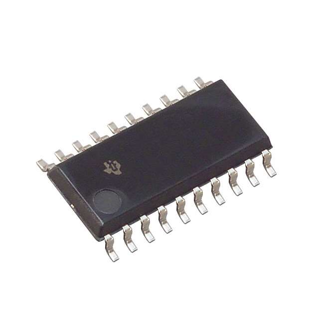
- Package: 20-pin small-outline integrated circuit (SOIC)
- Essence: Serial-to-parallel and parallel-to-serial data conversion
- Packaging/Quantity: Available in reels of 2500 units
Specifications
- Supply Voltage Range: 4.5V to 5.5V
- Operating Temperature Range: -40°C to +85°C
- Input Voltage Range: 0V to VCC
- Output Voltage Range: 0V to VCC
- Maximum Clock Frequency: 100MHz
- Number of Bits: 8
- Logic Family: TTL (Transistor-Transistor Logic)
Detailed Pin Configuration
- GND (Ground)
- QA (Output A)
- QB (Output B)
- QC (Output C)
- QD (Output D)
- QE (Output E)
- QF (Output F)
- QG (Output G)
- QH (Output H)
- SER (Serial Data Input)
- CLK (Clock Input)
- RCLK (Register Clock Input)
- SRCLR (Shift Register Clear Input)
- OE (Output Enable Input)
- MR (Master Reset Input)
- VCC (Supply Voltage)
- NC (No Connection)
- NC (No Connection)
- NC (No Connection)
- GND (Ground)
Functional Features
- Parallel-in/serial-out data conversion
- Storage capability for the shifted data
- High-speed operation
- Compatible with various logic families
- Multiple outputs for easy cascading
- Flexible control inputs for clearing and resetting
Advantages
- High-speed operation allows for efficient data transfer
- Versatile compatibility with different logic families
- Multiple outputs enable easy expansion and cascading
- Flexible control inputs provide convenient functionality
Disadvantages
- Limited number of bits (8) may not be sufficient for certain applications requiring larger data storage
- Requires external components for proper functioning, such as clock signal source and power supply
Working Principles
The SN74F299NSRG4 is a shift register IC that performs serial-to-parallel and parallel-to-serial data conversion. It consists of eight flip-flops that store the incoming data in parallel format and then shift it out in a serial manner. The clock input controls the shifting of data, while the register clock input enables the parallel loading of data into the flip-flops. The shift register clear input clears the stored data, and the output enable input activates or deactivates the outputs.
Detailed Application Field Plans
The SN74F299NSRG4 can be used in various applications, including:
- Serial data communication systems
- Data storage and retrieval systems
- Parallel-to-serial and serial-to-parallel data conversion
- Digital signal processing
- Microcontroller interfacing
- Industrial automation
- Telecommunications equipment
Detailed and Complete Alternative Models
- 74HC299: 8-bit parallel-in/serial-out shift register
- CD4021B: 8-stage static shift register
- SN54HC595: 8-bit serial-in/serial or parallel-out shift register
- CD4094B: 8-stage shift-and-store bus register
- 74LS164: 8-bit serial-in/parallel-out shift register
These alternative models offer similar functionality and can be considered as substitutes for the SN74F299NSRG4 depending on specific requirements and availability.
Word count: 474 words
قم بإدراج 10 أسئلة وإجابات شائعة تتعلق بتطبيق SN74F299NSRG4 في الحلول التقنية
Sure! Here are 10 common questions and answers related to the application of SN74F299NSRG4 in technical solutions:
Q: What is SN74F299NSRG4? A: SN74F299NSRG4 is a 8-bit universal shift/storage register with 3-state outputs, commonly used in digital systems.
Q: What are the key features of SN74F299NSRG4? A: Some key features include parallel-to-serial or serial-to-parallel data conversion, 3-state outputs for bus-oriented applications, and compatibility with various logic families.
Q: How can I use SN74F299NSRG4 in my circuit design? A: SN74F299NSRG4 can be used as a shift register, storage register, or a combination of both, depending on your specific requirements.
Q: What is the maximum clock frequency supported by SN74F299NSRG4? A: The maximum clock frequency supported by SN74F299NSRG4 is typically specified in the datasheet and depends on the operating conditions.
Q: Can I cascade multiple SN74F299NSRG4 devices together? A: Yes, you can cascade multiple SN74F299NSRG4 devices to increase the number of bits in your shift register or storage register.
Q: What is the power supply voltage range for SN74F299NSRG4? A: The power supply voltage range for SN74F299NSRG4 is typically specified in the datasheet and can vary depending on the specific device variant.
Q: Does SN74F299NSRG4 support 5V logic levels? A: Yes, SN74F299NSRG4 is compatible with 5V logic levels, making it suitable for use in both 3.3V and 5V systems.
Q: Can I use SN74F299NSRG4 in high-speed applications? A: Yes, SN74F299NSRG4 is designed to operate at high clock frequencies, making it suitable for high-speed applications.
Q: Are there any specific precautions I need to take while using SN74F299NSRG4? A: It is recommended to follow the guidelines provided in the datasheet, such as proper decoupling and grounding techniques, to ensure reliable operation.
Q: Where can I find more information about SN74F299NSRG4? A: You can find detailed information about SN74F299NSRG4 in the datasheet provided by the manufacturer or by contacting their technical support team.