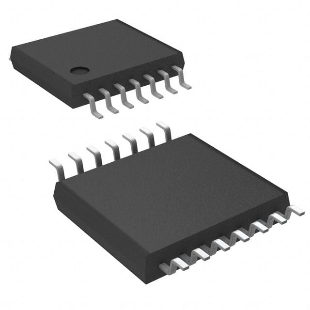
SN74LV125APWG4
Product Overview
- Category: Integrated Circuit (IC)
- Use: Buffer/Driver
- Characteristics: Low-voltage, Quad 3-state Non-inverting Buffer/Driver
- Package: TSSOP (Thin Shrink Small Outline Package)
- Essence: This IC is designed to provide non-inverting buffer/driver functionality with 3-state outputs.
- Packaging/Quantity: Available in reels of 2500 pieces.
Specifications
- Supply Voltage Range: 1.65V to 5.5V
- Input Voltage Range: 0V to VCC
- Output Voltage Range: 0V to VCC
- Maximum Operating Frequency: 100MHz
- Number of Channels: 4
- Output Current: ±12mA
- Propagation Delay Time: 6ns (typical)
Detailed Pin Configuration
The SN74LV125APWG4 has a total of 14 pins, which are assigned as follows:
- GND - Ground
- A1 - Input A1
- Y1 - Output Y1
- A2 - Input A2
- Y2 - Output Y2
- GND - Ground
- A3 - Input A3
- Y3 - Output Y3
- A4 - Input A4
- Y4 - Output Y4
- OE - Output Enable
- VCC - Power Supply
- GND - Ground
- GND - Ground
Functional Features
- Non-inverting buffer/driver functionality
- 3-state outputs for bus-oriented applications
- High-speed operation with low power consumption
- Wide supply voltage range allows compatibility with various systems
- ESD protection on all inputs and outputs
Advantages and Disadvantages
Advantages: - Non-inverting buffer/driver allows easy integration into existing systems - 3-state outputs enable bus sharing and reduce conflicts - High-speed operation ensures efficient data transfer - Wide supply voltage range provides flexibility in different applications - ESD protection enhances reliability
Disadvantages: - Limited number of channels (4) - Propagation delay time may affect timing-sensitive applications
Working Principles
The SN74LV125APWG4 is a quad non-inverting buffer/driver IC. It takes input signals from the A1 to A4 pins and provides corresponding non-inverted outputs on the Y1 to Y4 pins. The OE (Output Enable) pin controls the output state, allowing the outputs to be put in a high-impedance state when disabled.
Detailed Application Field Plans
The SN74LV125APWG4 is commonly used in various applications, including:
- Microcontroller interfacing: It can be used to interface microcontrollers with other devices, such as sensors, actuators, or displays.
- Data buses: The 3-state outputs make it suitable for use in bus-oriented systems, where multiple devices share a common data bus.
- Level shifting: It can be employed to shift logic levels between different voltage domains, ensuring compatibility between different parts of a system.
- Signal buffering: The IC can be used to amplify weak signals or provide isolation between different sections of a circuit.
Detailed and Complete Alternative Models
Some alternative models that offer similar functionality to the SN74LV125APWG4 are:
- SN74LVC125A: Low-voltage Quad 3-state Non-inverting Buffer/Driver with 5V Tolerant Inputs
- SN74HCT125: Quadruple Bus Buffer Gates with 3-state Outputs
- SN74LS125A: Quad 3-state Non-inverting Buffer/Driver
These alternatives can be considered based on specific requirements, such as voltage compatibility or speed.
In conclusion, the SN74LV125APWG4 is a versatile IC that provides non-inverting buffer/driver functionality with 3-state outputs. Its wide supply voltage range, high-speed operation, and ESD protection make it suitable for various applications in microcontroller interfacing, data buses, level shifting, and signal buffering.
Word count: 498
قم بإدراج 10 أسئلة وإجابات شائعة تتعلق بتطبيق SN74LV125APWG4 في الحلول التقنية
Sure! Here are 10 common questions and answers related to the application of SN74LV125APWG4 in technical solutions:
Q: What is SN74LV125APWG4? A: SN74LV125APWG4 is a quad bus buffer gate with 3-state outputs, commonly used for signal buffering and level shifting applications.
Q: What is the operating voltage range of SN74LV125APWG4? A: SN74LV125APWG4 operates within a voltage range of 1.65V to 5.5V.
Q: How many channels does SN74LV125APWG4 have? A: SN74LV125APWG4 has four independent channels, each with a separate input and output.
Q: What is the maximum output current of SN74LV125APWG4? A: The maximum output current per channel of SN74LV125APWG4 is typically 12mA.
Q: Can SN74LV125APWG4 be used for level shifting between different voltage domains? A: Yes, SN74LV125APWG4 can be used for level shifting between voltage domains due to its wide operating voltage range.
Q: Does SN74LV125APWG4 support 3-state outputs? A: Yes, SN74LV125APWG4 supports 3-state outputs, allowing multiple devices to share a common bus.
Q: What is the propagation delay of SN74LV125APWG4? A: The typical propagation delay of SN74LV125APWG4 is around 5ns.
Q: Can SN74LV125APWG4 be used in high-speed applications? A: Yes, SN74LV125APWG4 can be used in high-speed applications as it has a maximum operating frequency of 125MHz.
Q: Is SN74LV125APWG4 compatible with other logic families? A: Yes, SN74LV125APWG4 is compatible with various logic families such as TTL, CMOS, and LVTTL.
Q: What package does SN74LV125APWG4 come in? A: SN74LV125APWG4 is available in a TSSOP-14 package, which is a small surface-mount package with 14 pins.
Please note that the answers provided here are general and may vary depending on specific datasheet specifications or application requirements.


